


5V 4 Channel Relay Module with Optocoupler
5V 4 Channel Relay Module with Optocoupler
SKU: CT-0159
1 in stock
- 5V input voltage
- Comes with the optocouplers
- Provides the isolation to the MCU from the Load supply
- Low level trigger
- AC Load Supply : 10A@250V & 10A@120V
- DC Load Supply : 10A@240V & 10A@120V
- 4 separate LEDs for On/Off indication of the Relays
Couldn't load pickup availability
 Get it before .
 B2B customers can avail ₹23.64 ITC on this product.
 Free Shipping over ₹1299.
- Safe Handling
- Faster Shipping
- Easy Return
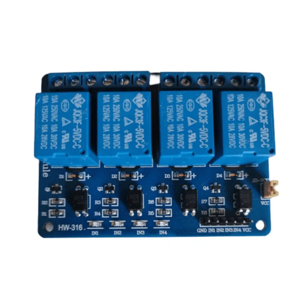
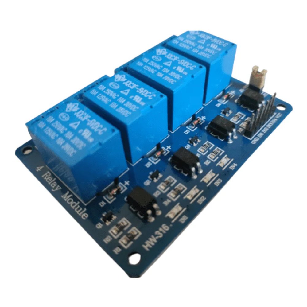
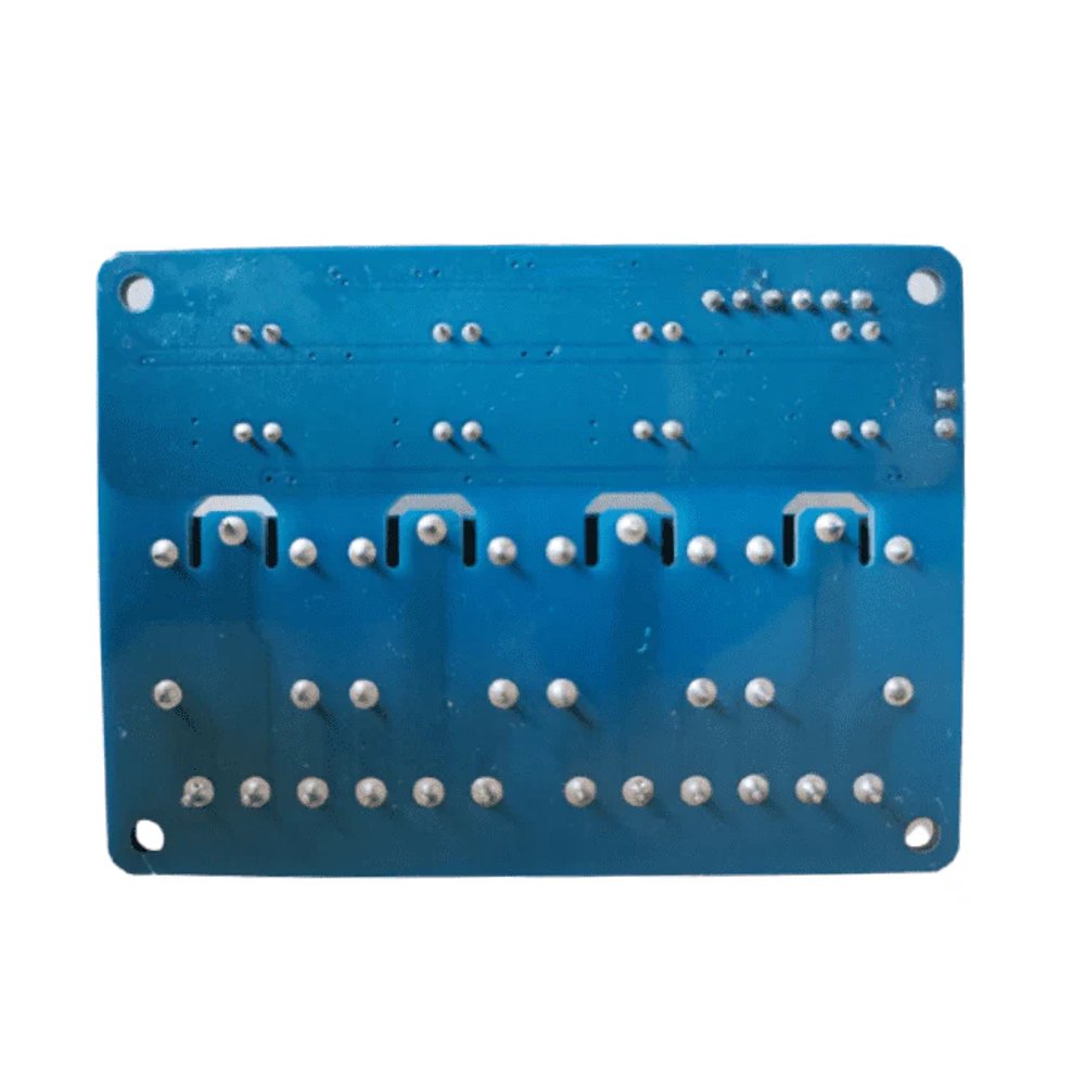
This 5V 4 Channel Relay has 4 separate relays. The module comes with the optocouplers, which enables input of the module to operate from on a supply other than the one used by the module. It is useful in high load and high noise environment. The operating Voltage of the module is 5V, which is needed for the relay operation, although it can be controlled directly with 3.3V or 5V logic signals from a microcontroller.
The Device has 6 control pins :
- VCC pin provides power to the optocouplers and, optionally, the relay’s electromagnet (explained below). Connect it to the 5V.
- GND is the common ground pin.
- IN1 - IN4 pins controls the relay.
There are 3 Output Pins :
- COM terminal should be connected to the device you want to control using Relay.
- NO terminal is Normally Open and it remains disconnected from the Relay when the relay is deactivated. It connects with the COM terminal when the relay gets activated. It should be connected to the device you want to control using Relay.
- NC terminal is normally closed. It remains disconnected from the Relay when the relay is activated. It connects with the COM terminal when the relay gets deactivated.
Power selection Pins :
The JD-VCC controls how the electromagnet of the relay will get the power from. If the jumper is connected between the JD-VCC and VCC, the relay's electromagnet will be powered from the VCC of the control pins. This arrangement will not isolate the microcontroller from the Load supply.
Otherwise, if you want to isolate the MCU from the AC load, do not connect the jumper between the JD-VCC and the VCC pins. In this case, you have to connect another power supply to these power pins. Connect 5V to the JD-VCC and GND to GND.
- JD-VCC pin powers the relay's electromagnet (no jumper). When the pin is shorted to the VCC (with jumper), the electromagnet is powered from the 5V on the control pins.
- VCC is used along with the JD-VCC to use the common power for the electromagnet and optocoupler. Keep the pin disconnected if the jumper is not used.
- GND is command GND pin.
Features :
- 5V input voltage
- Comes with the optocouplers
- Provides the isolation to the MCU from the Load supply
- Low level trigger
- AC Load Supply : 10A@250V & 10A@120V
- DC Load Supply : 10A@240V & 10A@120V
- 4 separate LEDs for On/Off indication of the Relays
Application :
- Lighting control system
- Automotive
- Home appliances
- motor drive control
- Industrial process controllers
| Number of Channels | 4 |
| Trigger Voltage | 5V |
| Switching Voltage (AC) | 10A@250V & 10A@120V |
| Switching Voltage (DC) | 10A@240V & 10A@120V |
| Contact Current Rating | 10Amps |
| Status indicator | 4 LEDs |
| Number of Output pins | 3 (NO, NC, COM) |
| Number of control pins | 6 (VCC, GND, IN1 - IN4) |
| Power supply pins | 2 (JD-VCC, VCC) |
| Product Dimesions | 75 x 55 x 17 mm |
| Product Weight | 40 grams |


